Designed for continuous removal of suspended particles from all types of liquids. Applications are in industrial plants plants using river, lake, well or sea water for cooling, descaling, bearing lubrication, spraying, quenching, and similar purposes. Pipeline sizes:8″-20″
Applications
Designed for continuous removal of suspended particles from all types of liquids. Applications are in industrial plants plants using river, lake, well or sea water for cooling, descaling, bearing lubrication, spraying, quenching, and similar purposes. Pipeline sizes:8″-20″ or larger
Liquids other than water, such as chemicals, acids, white water(paper mills), sewage plants, and ammonia flushing liquor (coke plants) can also be effectively strained.
Installation
Installation is made on the discharge side of a pump or in any piping system operating under a positive pressure. The minimum working pressure required to effectively clean the straining media is 20 psi. The strainer is compact with small face-to-face, width, and height dimensions. Installation can be made in a horizontal or vertical pipeline.
Design
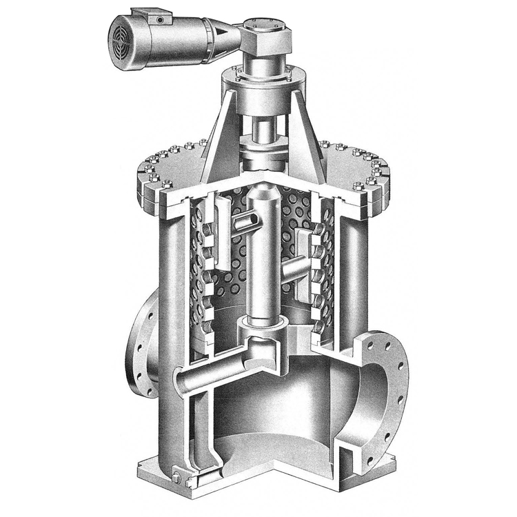
The strainer consists of a cylindrical drum with a number of threaded holes containing straining media. Within the drum is contained a rotor, which is essentially a hollow rotating shaft – supporting two pads extended on each side. These pads are flush with the inside of the drum surface.
Operation
The liquid to be strained enters the inlet connection located in the lower portion of the body and flows upward into the inner surface of the drum. The suspended particles are retained in the media pockets and the clean liquid passes through the media- leaving the body at the outlet connection located diametrically opposite the inlet.
Backwash
As the rotor sweeps past each row of straining media, a reversal of flow occurs, flushing the suspended particles from the media into the rotor and out through the backwash opening. This reversal of flow is caused by a pressure differential between the interior of the strainer and atmosphere. The backwash flow rate is exceptionally low and will vary, depending on the amount of suspended particles in the liquid. The backwash piping should discharge downward into an open funnel immediately after the backwash valve.
Automatic Backwash Control
In lieu of a manually operated valve on the backwash outlet line, an automatic control can be furnished to permit intermittent backflushing. This control consists of a motor or pneumatic cylinder operated ball valve actuated by a timer or a pressure differential switch (or both).
Download More Information:
Brochures:
Model AF